
How to Perform a Tolerance Stack Analysis: Step-by-step Guide
Aug 28, 2025 | 2 min read

In mechanical design, precision matters. Whether you’re building a simple bracket or a complex assembly, parts need to fit and function together seamlessly. That’s where tolerance stack analysis comes in.
A well-done 1D tolerance stack can help save time, reduce errors, improve product quality, and prevent costly surprises down the line.
In this guide, I’ll walk you through my 10-step process for performing a one-dimensional tolerance stack analysis. Along the way, I’ll explain how to choose the right analysis method—Worst Case (WC), Root Sum of Squares (RSS), or Modified RSS (MRSS)—and when each one fits best.
Objective
Learn how to quickly and accurately complete a 1D tolerance stack analysis using WC, RSS, and MRSS methods, and understand when each is appropriate.
Why It Matters
- Safety-critical parts require absolute certainty. There is no room for failure.
- Short stack paths (<5 dimensions) don’t follow normal distribution assumptions.
- RSS can be overly optimistic, so MRSS is often a more practical choice.
10 Steps to Building a Solid Tolerance Stack Analysis
These steps will guide you through the process from sketching your stack path to validating and documenting your analysis.
1. Start with a Picture
Sketch the part or assembly. Clearly show the start and end points of the dimension path. Hand-sketching a section view often works best to eliminate clutter.
You don’t have to be an expert at sketching to communicate the path you took in your assembly. Anyone who’s slightly familiar with the product should be able to see your sketch and understand what you’re dimensioning from and to. They may also use your drawings (dimensions used in stack-ups should exist on the drawing or some derivation of them).
2. Set Your Compass
Define the positive and negative directions. Be explicit to avoid confusion.
Standard convention states that up and right are positive; down and left are negative. However, if I’m calculating a gap or an intentional interference, I may change my direction to more clearly communicate negative values as interferences and positive values as gaps.
3. Walk the Path
Trace the dimension using vectors and labels. Mark every dimension in between.
This simple exercise can help you “short circuit” your stack path by eliminating unnecessary dimensions in the design drawings. More likely, it will help you choose better dimensions that are more useful to the design and function of the product.
4. Make a List (Check it Twice)
List all vectors in order, including their nominal values and symmetric tolerances. List all your nominal values in the same order you use in your stack path. The list should align step-by-step with your sketch so that anyone reviewing it can easily follow along.
5. Simple Arithmetic
Add all the nominal values to calculate the nominal stack dimension. This dimension should correlate to the measured dimension in your CAD model.
If there’s a mismatch, dig in: check for missed vectors, sign errors, or faulty assumptions.
6. Sum of Squares
Square each tolerance and sum them all. This forms the base for your RSS calculation.
7. Take the Square Root
Take the square root of the sum from Step 6 to get the RSS value. This may also be referred to as the quadratic value. I like to think that the RSS description is more easily understood.
8. Apply the Correction Factor
Multiply the RSS result by a correction factor to get the MRSS.
Some teams choose a generic factor between 1.4 and 1.8 as a coefficient to their RSS value because the RSS value assumes too tight a tolerance may be held when compared to empirical real-world results. At DISHER, I like to use a documented formula from Paul J. Drake, Jr.’s Dimensioning and Tolerancing Handbook that considers the number of contributors and the difference between RSS and WC values.
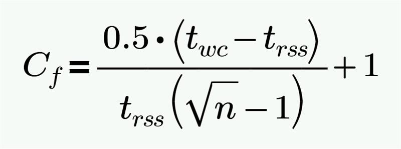
Source: Dimensioning and Tolerancing Handbook, Paul J. Drake, Jr., pg. 9-18
9. Gut Check
Pause and ask yourself:
- Do the results make sense?
- Is the gap acceptable?
- Which tolerance contributes the most?
- Can the path be shortened?
- Is this a safety-critical feature?
It’s far too common (especially when doing multiple tolerance analyses) to just accept the value that’s calculated without questioning your own results. For this reason, I suggest doing the calculations one day and revisiting them the next day to see if your values still make sense. This also gives me a fresh take on evaluating my own analysis from a reader’s perspective and not just from an author’s perspective.
10. Document Assumptions
Clearly state any assumptions you made (e.g., ignoring paint thickness, assuming perfect flatness, etc.). Assumptions are okay, so long as you document them clearly.
If your results don’t reflect what you see in the physical parts, it’s difficult to recall all the assumptions you made if you weren’t explicit about writing them down for the reader to follow. There may be common practices in your shop that aren’t common in other shops (e.g., bend radius on brake form tooling or minimum cut diameter may vary from shop to shop or even machine to machine).
Watch Out for These Common Mistakes
Here are some red flags to keep an eye out for as you build your stack:
- Skipping the picture or direction setup – Without a visual and clear direction, your analysis can be misinterpreted.
- Assuming normal distribution for small stacks – RSS is unreliable for paths with fewer than five dimensions. Use WC instead.
- Using RSS for safety-critical components – Even a tiny chance of failure is unacceptable here. Always use WC.
- Ignoring dominant contributors – Failing to identify which tolerance has the biggest impact can lead to poor design decisions.
- Not documenting assumptions – Omitting assumptions makes your analysis hard to verify and prone to misinterpretation.
- Overlooking the modification factor – MRSS is more realistic than RSS, so don’t skip this step.
Build and Analyze with Confidence
Clear thinking early on leads to cleaner outcomes. Taking the time to sketch your stack path, define directions, and run a proper tolerance analysis sets you and your team up for success. When in doubt, review your work through the eyes of someone else or ask a teammate for a quick gut check.
If you need help with a tolerance stack or a second set of eyes on your design, let’s talk. My team is ready to jump in where you need us.
Written By:

Dennis Smith
Design Engineer
DISHER Newsletter
Sign up to receive articles and insights, delivered monthly.
Schedule a no-committment project call
Reach out to discuss your project to find out if DISHER could be a good fit for you.